DFT Verification: 5 Steps to Improve Testability
I. Overview: DFT Static Sign-Off is Part of Design Sign-Off
Design for Testability (DFT) static sign-off is a crucial aspect of a modern DFT strategy. Starting DFT-rule checking early and continuing it throughout the entire design sign-off process is essential to help designers to improve coverage, while minimizing the risk of test-related bugs escaping into production.
This paper discusses five elements of DFT verification required to stop error escapes while maximizing engineering efficiency in tight project windows.
What is DFT Verification?
Design for Testability (DFT) verification is a process that checks RTL designs and netlists for errors related to testability features and logic that limit the controllability and/or observability of flip-flops and logic. Eliminating the DFT errors improves fault coverage and can reduce testing power requirements.
II. DFT Verification: 5 Steps to Improve Testability
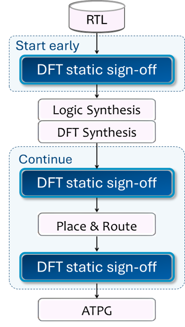
1. Start DFT verification early, continue at key stages
Failing to catch DFT errors early in the design process can lead to multiple iterations between design and DFT teams and/or costly bug fixes late in the design flow, potentially requiring chip re-spins. Even a single error can severely impact coverage.
Design teams and DFT experts benefit from incorporating DFT principles and addressing DFT issues early and continuously throughout the design process avoids time-consuming iterations. Key stages for DFT checks include:
- RTL design. Designers can identify and fix asynchronous set/reset, clock, and connectivity issues, e.g., by breaking combinational and sequential loops, connecting dangling nets, and by constraining some nets as constants. The DFT constraints must then be carried forward to DFT synthesis.
- Post-DFT synthesis. Verifying scan chain rule compliance with the DFT constraints applied to the design.
- Post-place & route. Addressing scan chain reordering and netlist modification issues before ATPG, BIST, and simulation.
Throughout the DFT static sign-off process, it’s crucial to ensure that neither the design nor the DFT constraints introduce new errors.
2. Check all test modes for each block
When partitioning a design for testing purposes, blocks are grouped based primarily on optimizing the balance between test power consumption and test time.
After partitioning, create multiple sets of constraints and apply rules to cover all targeted test modes. Running DFT rule checks for all test modes is necessary to ensure the design’s testability.
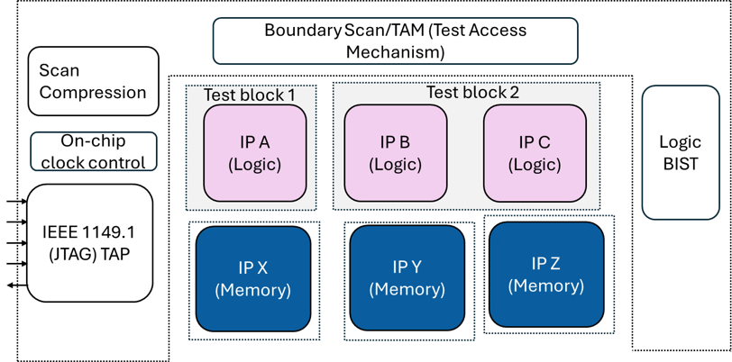
Scan tests serve two primary purposes. First is pass/fail manufacturing defect testing, with failed silicon rejected or down-binned into lower-quality bins. Second is defect diagnosis to pinpoint the precise defect location.
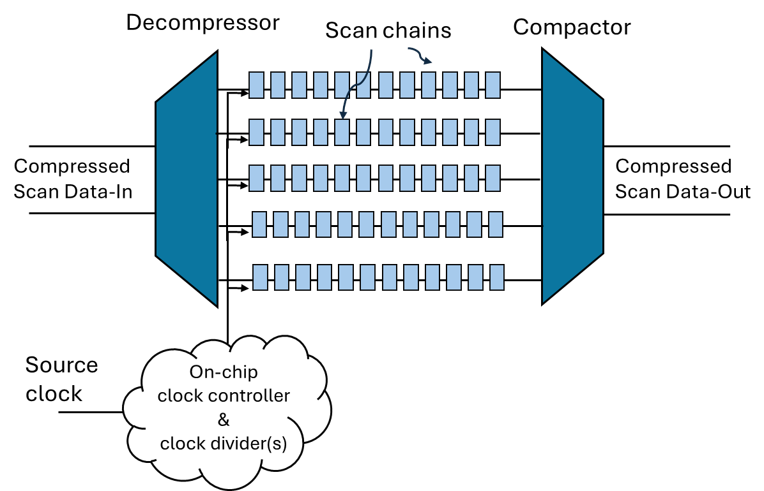
Below are three representative block-level test modes for scan testing:
- Test Mode 1. Compressed Scan — constrains logic IP blocks to enable parallel loading and unloading of scan chains for manufacturing test patterns. This reduces test data volume and time without compromising fault coverage; it is useful for pass/fail manufacturing tests.
- Test Mode 2. Uncompressed Scan — constrains the logic IP blocks to form daisy-chained scan chains for defect diagnosis patterns to identify failing scan flip-flops.
- Test Mode 3. At-speed Test — tests blocks at functional speed using on-chip clock or PLL.
After integration of DFT-clean IP blocks, engineers should verify all the test modes needed at the SoC level for: Detecting and diagnosing defects in interconnect between chip-level I/O & IP, as well as detecting and diagnosing defects internal to each IP.
3. Use broad & specialized DFT verification rules
Test integrity is affected by the ability to control asynchronous resets, test clocks, and test data during manufacturing tests.
Relevant DFT verification checks that can be performed at early RTL under test mode constraints include:
- Clock controllability from the tester clock
- Asynchronous reset controllability
- Asynchronous reset and clock glitch potential
- Data connectivity, including high sequential depth
Design for testability rule checking ensures that all flip flops and functional logic in the design are observable and controllable. Designers can fix errors by changing the functional logic, adding DFT constraints to the existing RTL logic, or both. Certain constraints will drive DFT synthesis to add new logic. Four representative rules are shown below.
Asynchronous reset controllability
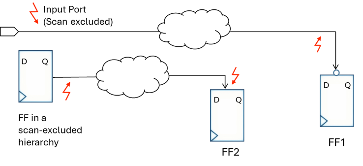
Rule: Ensure asynchronous reset/set inputs of flip-flops are controllable during scan capture.
Reason: The logic cone driving these inputs will not be observable through the flip-flop.
Sequential depth
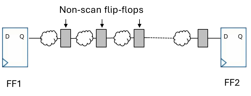
Rule: In capture mode, the sequential depth through non-scan flip-flops should not exceed the user-specified limit.
Reason: Excessive sequential depth during scan capture can produce loss of stuck-at and/or at-speed coverage.
Clock polarity

Rule: The path from a test source clock to a test clock must preserve the test clock’s polarity.
Reason: The flip-flops driven by the test clock would switch at unintended clock edges, invalidating the pattern timing assumptions and test results.
Test clock reconvergence glitch

Rule: A test clock should not fan out and reconverge with itself before reaching the clock input of a flip-flop.
Reason: The reconvergence of fanout branches with timing differences can cause an extra clock pulse or glitch during scan shift or scan capture.
4. Use precise, fine-grained DFT verification rules
Use precise, fine-grained rules to remove violation overlap and error duplication during DFT verification. Doing so dramatically reduces noise in violation reporting.
Avoid Overlap
Fine-grained rules should be defined such that there is no overlap between the rules, i.e., they are mutually exclusive. This achieves greater precision in reporting, while avoiding duplication in violations.
In the example shown, there are two mutually exclusive, finer-grain rules for glitches on asynchronous reset, rather than one broad rule.
One broad rule:
– The logic cone driving the asynchronous reset input should not produce a glitch.
Two fine-grained rules:
– Rule 1: The logic cone driving the asynchronous reset input of a flop cannot have internal convergence between two glitch sources.
– Rule 2: The logic cone driving the asynchronous reset input of a flop cannot have internal reconvergence.
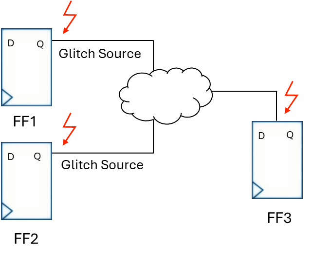
1. Asynchronous reset convergence glitch
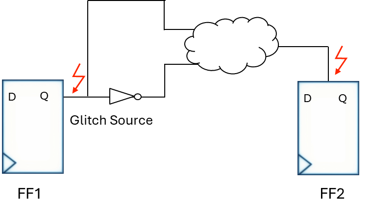
2. Asynchronous reset reconvergence glitch
Avoid duplicate violations
Create rules such that there are no duplicate violations reported for the same error.
For example, this one precise test clock glitch rule will ensure there is only one violation reported:
- Two or more test clocks should not converge while driving a flip-flop’s clock input.
In contrast, the rule below produces duplicate violations:
- Test clock pairs cannot converge before reaching a downstream flip-flop.

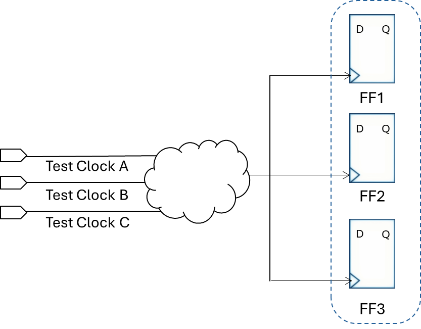
Test clock glitch convergence
This is because a flip-flop whose clock input is driven by a combinational logic cloud fed by test clocks A, B, and C will be reported three times — once for each of the converging pairs (A,B), (A,C), and (B,C).
This would result in a noisy report, as only one fix is needed, which is to constrain the logic cloud so that only one test clock reaches the clock input of the flip-flop.
Group errors by root cause
To maximize efficiency and scalability in fixing DFT errors, the goal should be to fix the root cause of the errors, instead of the error endpoints.
The test clock glitch convergence shown causes one convergence point to fan out to three different flip-flops — producing three DFT errors. By grouping these errors based on that root cause, the engineer will only need to apply one fix to ensure that no clock glitch can reach the destination flip-flops through the convergence point.
Judiciously apply functional analysis
Although functional analysis adds memory and runtime, it can be applied opportunistically when the accuracy gains merit it. For example, if there is a convergence between two glitch sources, and functional analysis shows only one active glitch source, then it should not be reported as a glitch convergence error.
This would apply to both clock glitches and asynchronous reset glitches, minimizing false positives and providing lower-noise reporting.
5. Tool usability can make or break a DFT methodology
To establish a widely adopted DFT verification methodology, it is important to incorporate a tool that is highly usable by the design team, minimizing the designer effort and their risk of error.
Below are several key metrics to consider when evaluating a DFT static sign-off tool.
![]()
Comprehensive Rule Set
The tool should include both broad and specialized rules to avoid missing DFT issues. Additionally, the rules should cover multiple design stages, including RTL, post synthesis, and post place & route.
![]()
Analyzes all test modes in one run
The most efficient way to check all specified test modes is to do the analysis in a single run. This can reduce static sign-off time by several weeks by reducing setup time, speeding up runtime, and enabling consolidated, hierarchical reporting.
![]()
Low-Noise Reporting
For greater precision in violation reporting, fine-grained rules should be defined such that they are each mutually exclusive, with no overlap. Precise rules should also not report duplicate violations for the same error. Further, functional analysis can be opportunistically applied to reduce false positives.
![]()
Finds Error Root Causes
A tool that identifies root cause errors and groups the violations accordingly is the most efficient way to address issues at all destination points. For example, an incorrectly constrained single reset source may fan out to a large number of asynchronous flip-flop resets, which may lead to an asynchronous reset error at each destination flip-flop.
![]()
Plugs into multi-vendor DFT flows
A DFT static sign-off tool that easily plugs into multi-vendor DFT flows enhances flexibility, allowing designers to utilize the best features from multiple vendors. This approach improves test coverage and enables tailored solutions that align with specific testing requirements.

Fast Setup Time
Fast tool setup time is crucial as it significantly accelerates the DFT verification process. When a tool can be deployed in hours instead of weeks, teams can more quickly identify and address testability issues. This agility enhances designer productivity and shortens the overall development cycle.
III. Conclusion: Eliminate DFT errors while improving coverage
DFT static sign-off is becoming a fundamental part of the design sign-off flow. Engineers are starting early, with emphasis on efficiently eliminating DFT errors within tight project windows.
This approach enables development teams to meet growing low defects per million requirements for applications such as automotive and aerospace applications, as well as a high defect diagnosis capability for new designs and/or process nodes.
About Real Intent Meridian DFT
Real Intent Meridian DFT multimode design for testability tool meets all key DFT verification metrics discussed above, eliminating missed errors while minimizing designer effort.
1. Has comprehensive rulesets across multiple design stages.
2. Analyzes all test modes in one run.
3. Has precise, fine-grained rules.
4. Groups errors by root cause.
5. Plugs into multi-vendor DFT flows.
6. Tool setup takes only hours instead of weeks.

ABOUT THE AUTHOR
Prakash Narain, President & CEO of Real Intent
Dr. Prakash Narain shifted Real Intent’s technology focus to Static Sign-Off to better tackle verification inefficiencies back in 2010. Since then, Prakash has expanded this effort to now offer a broad set of tools focused specifically on different static sign-off domains, including CDC, RDC, DFT and others — with more coming.
His career spans IBM, AMD, and Sun where he had hands-on experience with all aspects of IC design, CAD tools, design and methodologies. He was the project leader for test and verification for Sun’s UltraSPARC III, and an architect of AMD’s Mercury Design System. He has architected and developed CAD tools for test and verification for IBM EDA.
Dr. Narain has a Ph.D. from the University of Illinois at Champaign-Urbana where his thesis focus was on algorithms for high level testing and verification.
